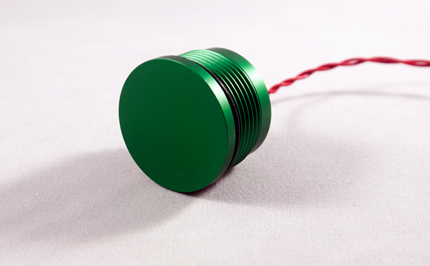
They do however work with thin surgical gloves or specially designed conductive fibre gloves that will allow a charge to be passed from the hand to the switch. Pricewise, capacitive switches are typically cheaper than piezo switches from a raw materials perspectiveĪ user wearing thick gloves cannot operate a capacitive switch. So for devices that are meant to react only to human touch, then the capacitive touch switch is ideal for this purpose.Ĭapacitive switches are used in a wide selection of applications, from medical and laboratory equipment and food processing machinery to consumer applications such as appliances, vending machines and lift controls. The difference between the device itself and the fingertip is sensed, thereby triggering the switch.Ī piezo switch senses touch force or relies on a small force, while capacitive switches require a charge or electrode, typically generated from human touch. The switch uses body capacitance, making use of the electrical charge naturally carried by the human body. On the other hand, a capacitive switch, also known as a capacitance switch, requires just one electrode, which can be placed behind a non-conductive panel. While there are no mechanical moving parts within the switch, it does require sufficient pressure to be applied in order to deflect the ceramic layer within. The word piezo is derived from the Greek piezein, which means to squeeze or press. It reacts to the force of being touched and generates an electric charge, which effectively sends a signal that the button has been pushed.Ī piezo switch relies on mechanical displacement or bending of piezo ceramic - also known as the piezoelectric effect. The durability of these switches means they can withstand millions of actuations and require little to no maintenance.Ī piezo is a small disc comprised of two layers an inner ceramic layer and an outer layer usually made from a metallic substance. Typically they are installed flush with the control panel, and with no moving parts they are often highly wear-resistant, dustproof, waterproof and suitable for repetitive operation. I need to go outside and asked my PS for help.Both types of switches are usually comprised of flat, metallic discs, sometimes surrounded by an illuminated ring that lights up when the switch is activated. So next time I came back and found my pictures ready for more "final" strokes! One thing not perfect though, is that I cannot "paint" the objects. Another good thing is that the RpiSO CircuitLab account tlfong01 is automatically created for me. My masterpiece was automatically inserted here, with the HTML lines inserted along, no need to go outside to ask Imgur for help. I dragged and pasted the symbols, draw connecting wires, and finally saved and inserted. Now I am trying to use the RpiSO's built in CircuitLab schematic editor to draw my piezo toy. I surprisingly found it as high as 30V! This would fry both the MCP3008 and and it master Rpi!Ĭonclusion: Zener diode is absolutely necessary! I was curious to know how high would be the piezo output voltage, without clamping it with a Zener diode. (A) Piezo with 1M, no Zener, One slight finger tap gives 30V peak (2) MCP3008 SPI 8 Channel 10 Bit ADC Datasheet - MicroChip Great for: Acoustic Instrument Pickups, Stomp Boxes, Contact Mics, (1) Piezo Pickup Transducer 27mm Contact Microphone Trigger - Discs Elements for Acoustic Instrument: Guitar, Drum, CBG etc. Now the piezo also outputs audio range signals, so I am thinking of doing the same thing. I once played with electromagnetic buzzer and used a little audio amplifier to amplifier the buzzer audio output. Anyway, I think the output amplitude under 5V and period of about 500mS good for MCP3008 to do conversion. I tested the piezo disk torn down from another piezo buzzer and found the finger tapping output signal of a different shape from the first one. Is disconnected by a careless newbie mistake, any high pulse generatedįrom piezo will not travel to the MCP3008, frying it and its master Rpi. In other words, MCP3008 isĭirectly connected to Zener (at points X, Y of picture below), NOT to piezo (points A, B). Note - I have first connected the Zener diode to the Piezo, and then The wave packet is less than 500mS long, amplitude smaller than 5V. So next step is to try to use MCP3008 to sample the signal.

The very high spike gets clamped down, and the following smaller wavelets look OK. Now I am using a 5V Zener diode to clamp the 30V+ piezo signal to under 5V. If the same PSU is used to power Rpi, than there is a risk of frying the Rpi.

This concludes that piezo output can burst many times up to 30V beyond 5V power. I found without the Zener, the piezo output spikes +-30V.
#PIEZO BUTTONS SERIES#
I googled and found other circuits using a 5V PSU and connects 1M and piezo in series across the PSU.


 0 kommentar(er)
